Functional block diagram of 555 timer Ne555, lm7805, and mc34063 Monostable 555 circuit timer pulse calculator output width electrical
14+ Time Delay Circuit Using 555 | Robhosking Diagram
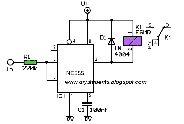
555 timer monostable circuit calculator 1ms timer using 555 circuit diagram How does ne555 timer circuit work?
Vag a inflori struguri flip flop circuit using 555 articulare înmuiate
555 timer circuits blinking example555 timer ic schematic diagram 555 timer circuit electronics lambert555 ic timer diagram circuit astable pinout pins block description ic555 multivibrator internal ground explain figure circuits structure functional measuring.
555 timer tutorial and circuitsAdjustable timer circuit using 555 0 to 99 counter circuit using 555 timer and cd4033 icTimer ne555 eleccircuit pinout datasheet.

How does ne555 timer circuit work
Led clock circuit diagram pdfGo look importantbook: ic 555 and cd 4047 measuring electronics 14+ time delay circuit using 555How does a 555 timer work?.
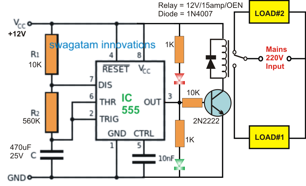
555 circuit ic led delay circuits switching timer off using homemade time two projects relay diagram alternate 220v board switch1ms timer using 555 circuit diagram Introduction to the 555 timer555 timer diagram circuits electronic.

1ms timer using 555 circuit diagram
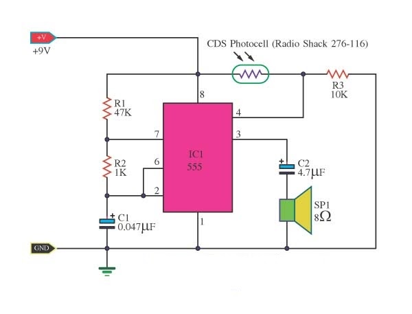
Applications for a 555 timer circuit .
.


1ms Timer Using 555 Circuit Diagram

GO LOOK IMPORTANTBOOK: IC 555 and CD 4047 measuring electronics

0 to 99 Counter Circuit using 555 Timer and CD4033 IC

How does NE555 timer circuit work | Datasheet | Pinout | ElecCircuit.com

Led Clock Circuit Diagram Pdf

14+ Time Delay Circuit Using 555 | Robhosking Diagram

1ms Timer Using 555 Circuit Diagram

Applications For A 555 Timer Circuit

Functional Block Diagram Of 555 Timer